Introduction
The history of timepieces dates back to ancient civilizations such as the Ancient Egypt, where obelisks were used to track the movement of the sun. Ancient timekeeping devices included sun dials, candle clocks, water clocks and hourglasses.
In the 14th century, the first mechanical clocks were invented and their accuracy continuously improved through multiple refinements such as the invention of the mainspring, the balance spring, and the pendulum.
The invention of the much simpler, inexpensive and more accurate quartz timepieces, mechanical timepieces began to fall into disuse. This caused a crisis in the Swiss watchmaking industry, and plunged the industry to the point that between 1970 and 1983 the number of Swiss watchmakers dropped from 1,600 to 600. The crisis drove mechanical watchmakers to focus on the higher end market to the point that mechanical watches became luxury goods, appreciated for their craftsmanship, precision engineering and aesthetic appeal.
In this post I will show how to use piezo-accelerometer sensor to measure the accuracy and analyze the vibration of a mechanical clock.
Mechanical Timepiece Ticking
The main components of a mechanical timepiece are: the power source, the wheel train, the escapement and the oscillator. The power source can be a mainspring or a suspended weight, and its purpose is to store and deliver energy to the wheel train. The wheel train is made of multiple gears that through different gear ratios move the different hands of the timepiece. The train wheel is connected to the escapement wheel, which is a mechanism that allows the wheel train to advance a fixed amount at each half-oscillation of the oscillator. The escapement wheel also transfers energy to the oscillator so that it stays oscillating while there is energy in the power source. The oscillator is the timekeeping element, and its purpose is to oscillate at a constant frequency, it can be either a balance wheel or a pendulum.
Mechanical timepieces generate a characteristic ticking sound when the escapement wheel is suddenly stopped by the pallet at each half-oscillation of the oscillator. Ticking rates typically go from 4 up to 8 ticks per second, and by measuring their rate it is possible to measure the accuracy of a timepiece and evaluate if it requires calibration.
The next video shows briefly how every major component of a mechanical wristwatch works.
Hardware Setup
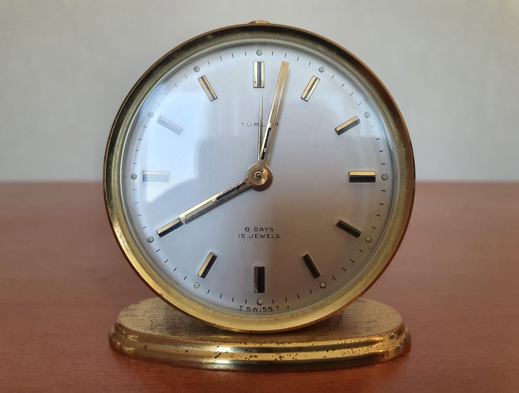
The experiments were performed on a swiss mechanical clock from around 1960 with a ticking rate of 5 ticks per second. I am not aware of any calibration of the clock so I did not have any expectation in its accuracy.
The setup used 4 elements: A piezo-accelerometer/vibration sensor (Kemet VS-BV203), a data acquisition device (DAQ), a computer and the clock.

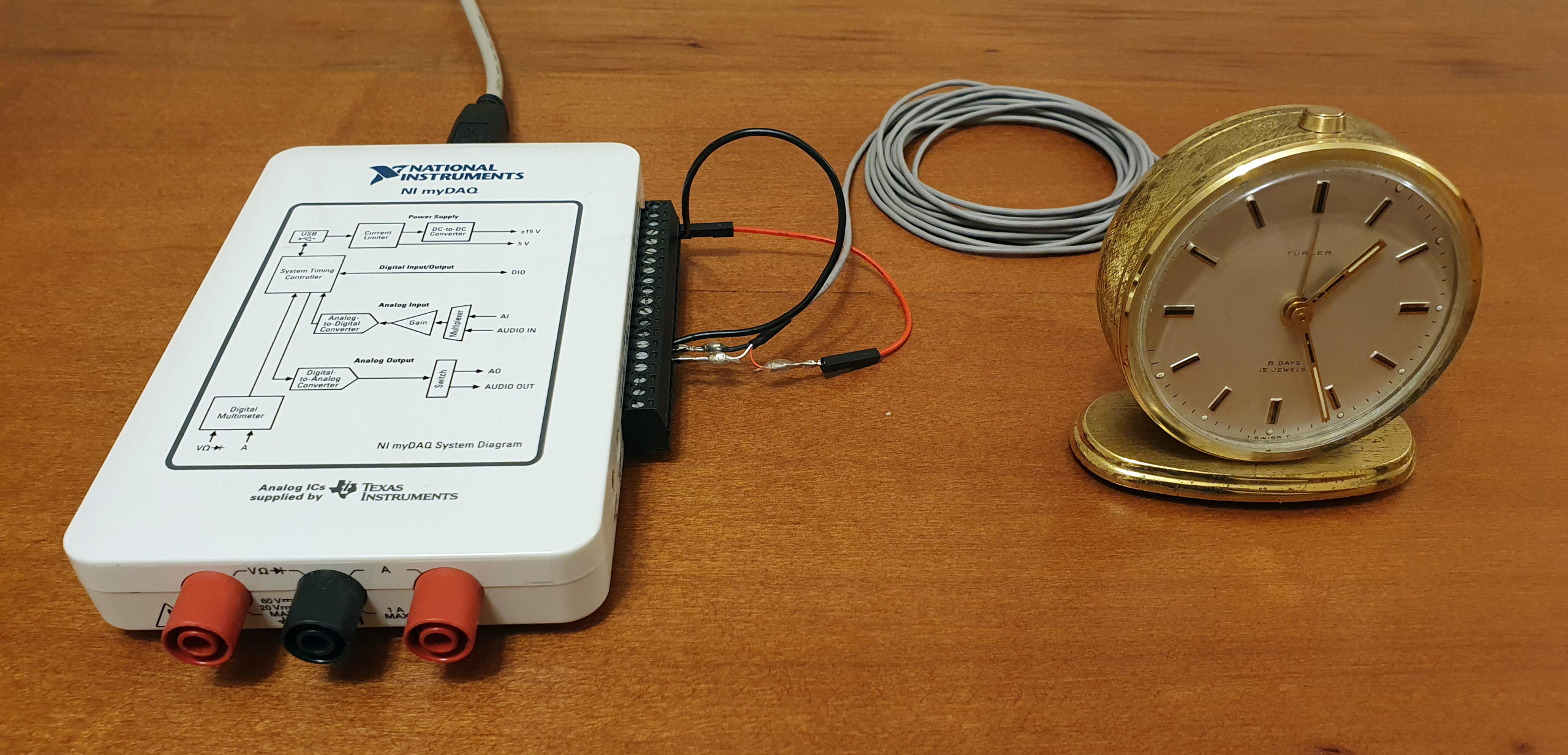
The vibration sensor was laid below the clock. No glue was required to capture a high SNR ticking vibration signal.
Accuracy Measurement
A full clock cycle takes 12 hours, so I decided to capture 24 h in order to compare the two cycles against each other. The capture was made at 200 ksps (NI myDAQ‘s maximum sampling frequency) with the clock fully wound up.
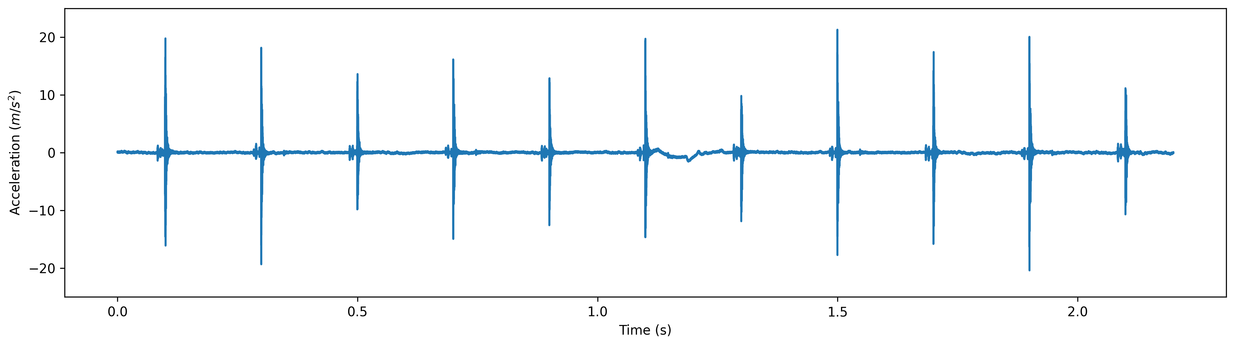
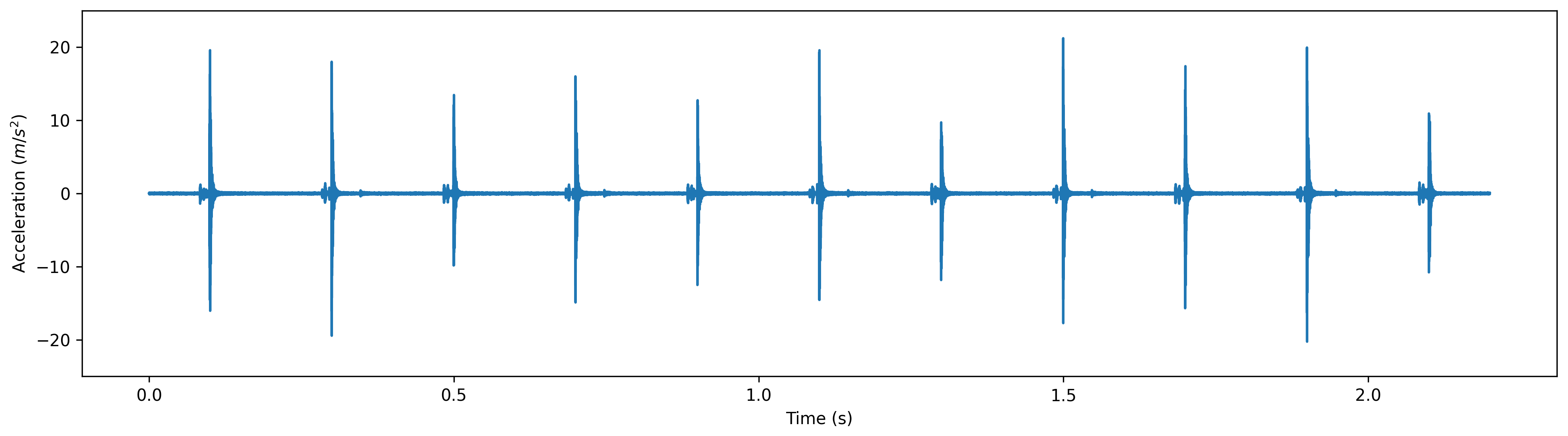
The captured vibration time series showed white noise and a low frequency (< 1khz) noise component (apparently originated from the DAQ power supply). The high signal to noise ratio (SNR) of the signal did not make it necessary to filter the signal before applying the tick detection algorithm.
The algorithm to detect the moment when ticks occur can be summarized like this:
- Detect the first tick of the time series by finding the highest acceleration at the beginning of the time series within a ticking period (0.2 s) window.
- Repeat until the complete time series has been processed: Get the next tick by finding the highest acceleration within a small scanning window (0.02 s) one ticking period (0.2 s) after the last detected tick.
After detecting a little bit more than 432,000 ticks, I plotted the clock drift of the first and second cycle (using the DAQ internal clock as reference).
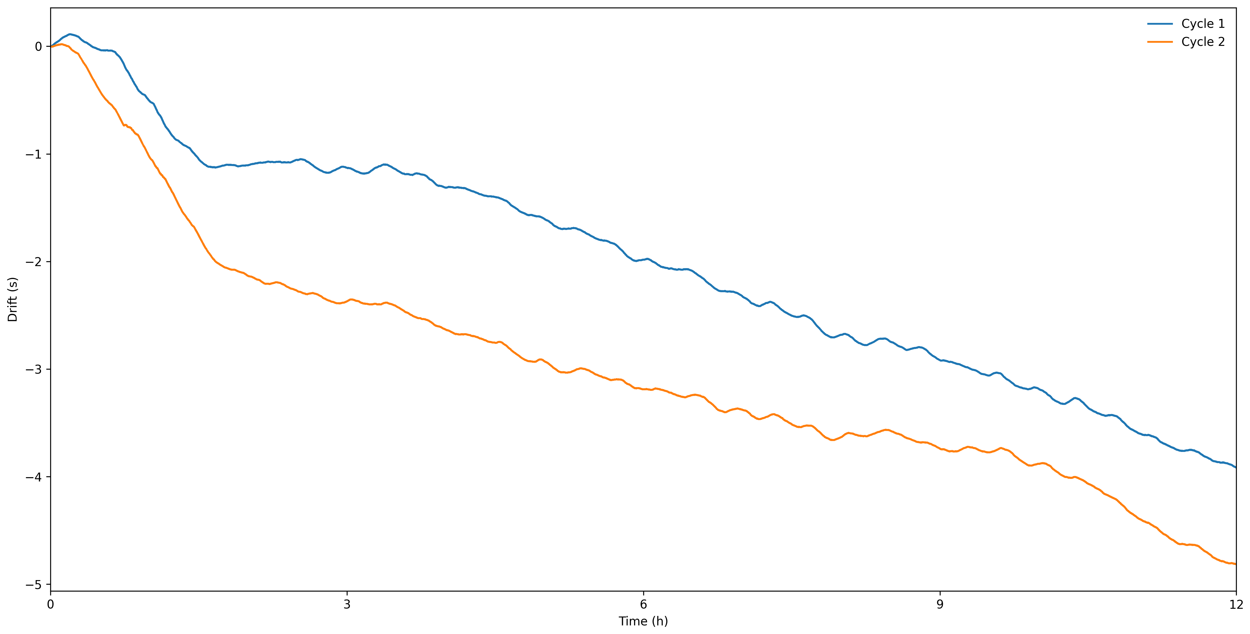
The generated plot revealed a few interesting aspects of the mechanical timepiece.
Except for very shorts periods of time, the mechanical clock tended to run slower than the reference DAQ clock. As the mainspring unwinds, its torque diminishes, and this reduces the clock ticking even further.
The mechanical clock drifted ~3.9 s and ~4.8 s from the DAQ clock on the first and second cycle respectively. Assuming that the DAQ clock is accurate, a daily drift of ~8.7 s would be relatively good for a mechanical clock, but the performance would eventually continue to degrade as the mainspring continues to unwind (the clock can run up to 8 days when completely wound up).
At every cycle, between 12:00 and 1:30, the clock tends to run slower than during the rest of the cycle. This is likely caused by friction associated to gears that rotate once every 12 h. The drifting waveform also contains a small amplitude oscillatory component that probably is associated to gears that rotate a few times per hour.
Vibration Analysis
When visualizing time series in the time-frequency domain it is easier to detect certain patterns that otherwise would be hard to detect in the time domain.
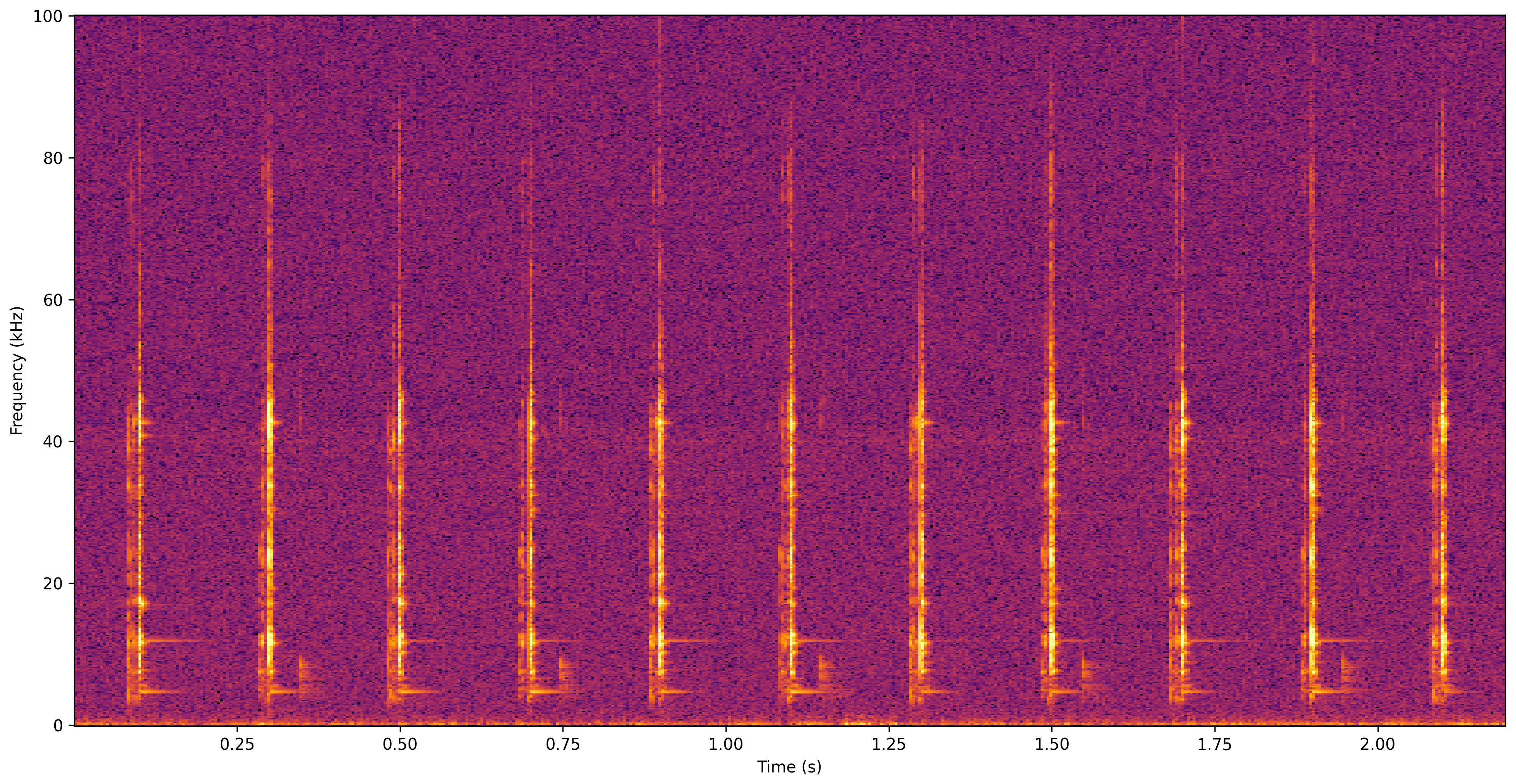
There are a couple of interesting observations that can be made from the generated spectrogram.
Clocks generate ticking sounds through the impact between the escapement wheel teeth and the pallets. Impact waveforms approximate to the Dirac delta function, so they cover a wide frequency range. The spectrogram frequency components that follow each impact are result of the resonance of components of the clock (probably the escapement mechanism parts).
The clock ticks every half-oscillation, so at every tick the pallet and the rotation direction of the balance wheel change. This generates a different ticking pattern between consecutive ticks.
The white noise and the low frequency noise are also quite visible in the spectrogram, and also easy to notice when listening to the sound produced by the time series.
Unfiltered ticking sound
To remove the low frequency noise I applied a high-pass 1 kHz cutoff frequency, 5th order Bessel filter.
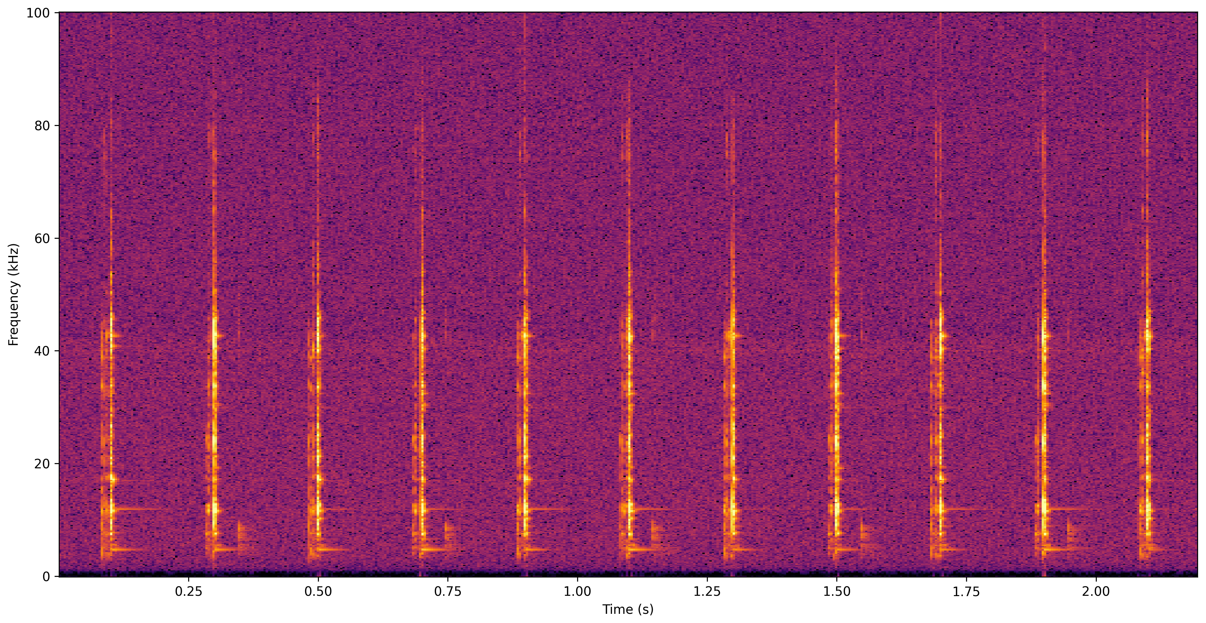
Since the ticking sound spectrum goes from ~2 kHz up to ~90 kHz, it was not affected by the filter. To remove the white noise I used the noise reduction filter of Audacity, and this considerably improved the quality of the audio.
I also slowed down the playback speed to 1/5 to make the ultrasonic ticking spectrum components hearable, and to make it easier to hear the difference between the ticking sound generated by each pallet.
Filtered normal playback ticking sound
Filtered slow playback (1/5) ticking sound
Analog to the way that each pallet generates a different audio signature, I hypothesized that each tooth of the escapement wheel would generate a characteristic vibration signature when impacted by the pallets.
If the hypothesis is true, the matching of vibration signatures separated by a complete escapement wheel rotation should be better than of non-complete rotations (e.g., after advancing 1 tooth).
To test the hypothesis, I performed an autocorrelation of the spectrogram in the range of 2 to 100 kHz.

The plot shows cycles with 3 different periods:
Every 0.2 s there is a tick, and this generates autocorrelation spikes (> 0.5) at its multiples.
Every 0.4 s (2 ticks) the same pallets impact the teeth of the escapement wheel, this tends to generate higher autocorrelations at their multiples.
Every 6 s (30 cycles) the autocorrelations are the highest (> 0.7), strongly suggesting that same teeth are being impacted by the same pallets (i.e., an escapement wheel with 15 teeth made a full rotation).
Conclusion
My initial plan was to measure the accuracy of a mechanical clock so that I could calibrate it. I evaluated the first 24 h past a full winding of the clock, but a better evaluation would require recording the clock as it completely unwinds for 8 days and a better reference clock.
As explained before, the mainspring torque affects the ticking speed of the clock, so how one plans to wind up the clock is relevant when deciding how to calibrate it. Ideally the clock should be calibrated so that the average ticking rate is closest to its specification. If the clock is calibrated so that it averages its specification when winding it up once a day, it will lag behind the actual time if it is wound up once a week. Calibrating the clock for a weekly winding also has the effect that the torque variation during the unwinding will be much greater than if it is done on daily basis, this would lead to a greater variation of the ticking rate (even though its weekly average is close to the specification).
The accuracy measurement of a clock is limited by the accuracy of the reference clock, which for the DAQ is 100 PPM. This is insufficient, as in 24 h the reference could drift as much as 8.64 s. A solution to this could be to use 2 ports of the DAQ, one would be fed with the mechanical clock vibration signal and the other with an accurate reference clock signal. Then through software, the reference signal would be used to time the vibration signal. An alternative better solution would be to use an accurate reference clock to time the data conversion itself, but that might harder to implement.
While evaluating the accuracy of the clock I found that there was much more to explore in the time series. One surprising discovery was that it is possible to infer the inner workings of the clock through analysis of the vibration patterns. Similar to how motor vibration analysis can be used to detect faults, vibration analysis of a mechanical timepiece can be used to measure their accuracy, but also to infer its characteristics and faults.
The code is available on GitHub.