Introduction
DC-DC converters are devices that convert a source at one DC voltage into another. They can be classified in many ways, such as between linear and switching, between step-up and step-down, based on their topology, and so on.
Depending on the application one may prioritize different figures of merit. For instance, for IoT applications the efficiency is one of the most critical figures, as it affects the life of the battery, while for other applications, the quality of the output could be more important. These two figures can be relevant when deciding what type of converter to use, a switching regulator offers high efficiency but a noisier output, while a linear converters sacrifices efficiency for higher quality output.
In this post I will show how I measured the efficiency and output voltage of a step-down converter using a pair of source measure units (SMUs).
Maxim Integrated MAXM17503
The Maxim Integrated MAXM17503 is synchronous step-down DC-DC power module. It operates at input voltages of 4.5 V to 60 V, can deliver up to 2.5 A and can reach efficiencies higher than 90%. The module can be configured to operate in 3 modes: pulse-width modulation (PWM), pulse-frequency modulation (PFM) and discontinuous conduction mode (DCM).
The PWM mode has low efficiency at light currents, but switches at a constant frequency. This is useful in applications sensitive to switching frequency changes.
The PFM mode is efficient at very light loads, but at the cost of a lower quality of the output. It also does not keep the switching frequency constant.
The DCM mode features constant frequency switching and provides a light load efficiency in-between the PWM and PFM mode.
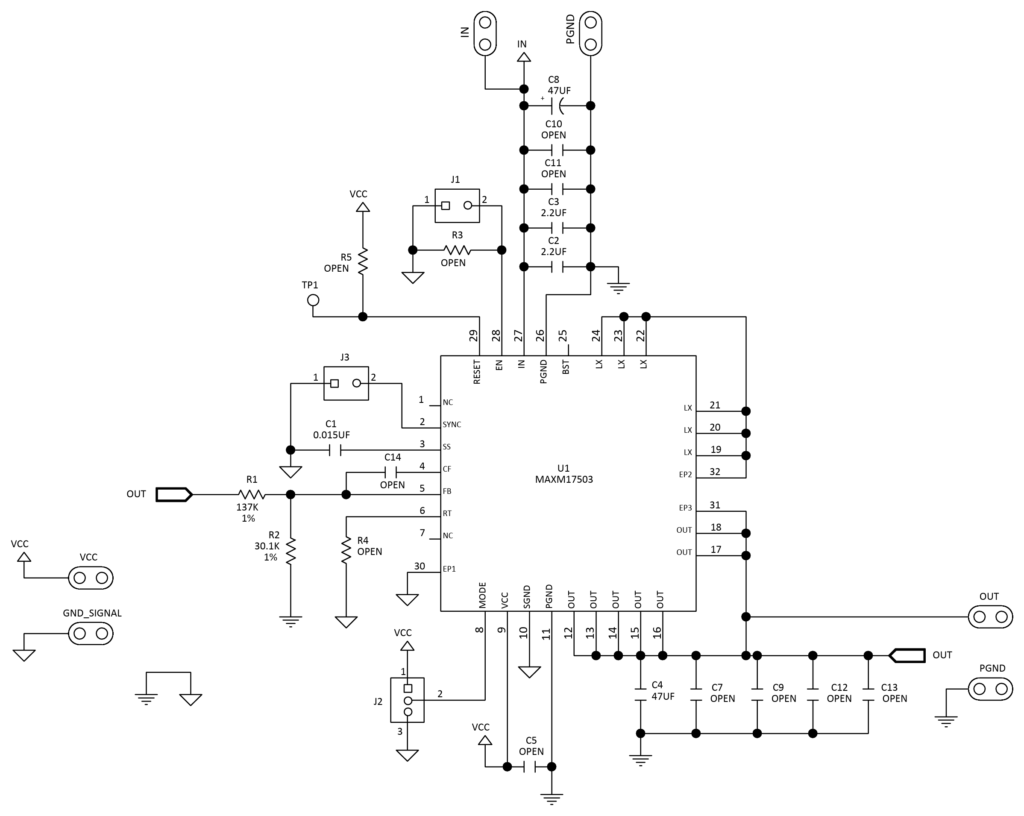
To evaluate the MAXM17503 I used the MAXM17503EVKIT evaluation kit, which is a kit that configured to operate at a switching frequency of 500 kHz and to produce a 5 V output. The kit provides configuration jumpers and makes it possible to test the IC on PWM, PFM and DCM operation modes (J2).
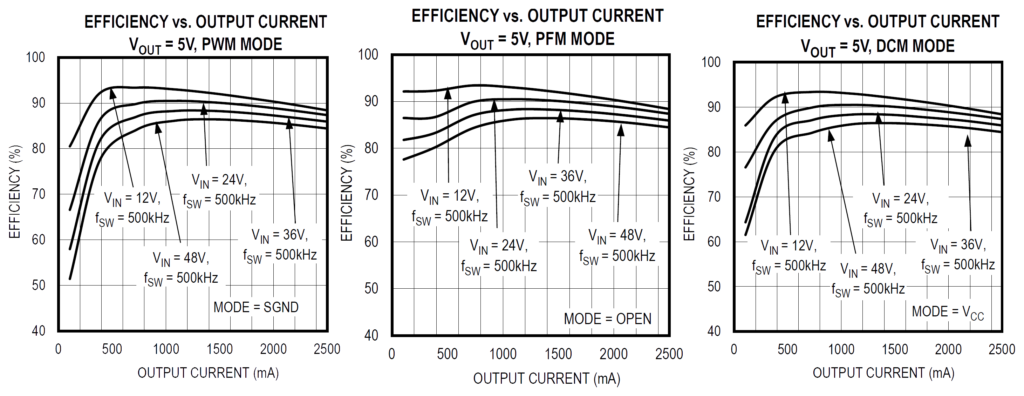
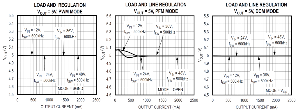
The evaluation kit datasheet provides efficiency and \(V_\mathrm{out}\) plots for different \(V_\mathrm{in}\), \(I_\mathrm{out}\) and modes of operation.
Even though the datasheet plots show the efficiency and \(V_\mathrm{out}\) at different conditions, they still have some shortcomings:
- The \(I_\mathrm{out}\) scale is linear, so it is hard to visualize what occurs at very low currents.
- The efficiency at \(I_\mathrm{out}\) <~100 mA is not plotted.
- It is not clear what happens at \(V_\mathrm{in}\) values not shown in the plots (e.g., <12 V or >48 V).
- The poorly selected \(V_\mathrm{out}\) scale makes it impossible to compare the effect of \(V_\mathrm{in}\) in the PWM and DCM modes. These plots also do not show if there are any differences between these two modes.
Let’s make some measurements to get a better picture of how the operation mode, \(V_\mathrm{in}\) and \(I_\mathrm{out}\) affect efficiency and \(V_\mathrm{out}\).
Measuring Setup
The efficiency and voltage output of the device can be easily measured with a power supply and an electronic load, but this approach does not provide much current dynamic range. By adding more instruments and complexity it is possible to overcome these limitations, but probably the easiest way is with a pair of SMUs (or a single 2 channel SMU).
I own 2 SMUs, a Keithley 2450 and a Rhode & Schwarz NGU401, each with different voltage and current limits. The voltage limits are ±200 V (⩽ 0.1 A) for the 2450 and ±20 V (⩽ 3A) for the NGU401. While the current limits are ±1 A (⩽ 20 V) for the 2450 and ±8 A (⩽ 6 V) for the NGU401.
Considering that the MAXM1703EVKIT can source up to 2.5 A, it made sense to use the NGU401 as a sink and the 2450 as a source.
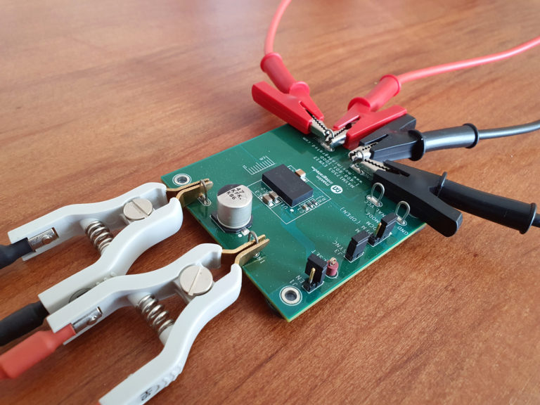
To get accurate measurements at high currents, the device was connected using 4-wire connections at the input and output.
SMU Control
Both SMUs can be programmed to perform sweeps automatically, but I decided to program the controller to perform the sweeps manually, to keep the synchronization of the instruments simple.
I wrote the control program in Python and used PyVisa to control the SMUs through VISA calls. The program swept \(V_\mathrm{in}\) from 6 V to 20 V and at \(I_\mathrm{out}\) from 25 µA to 2.5 A.
\(V_\mathrm{in}\) was swept in the inner loop and \(I_\mathrm{out}\) in the outer loop so that the power consumption changed slowly (as it depends on \(I_\mathrm{out}\)). \(V_\mathrm{in}\) was swept linearly and \(I_\mathrm{out}\) exponentially using 50 steps for each sweep. I gave 2 s to the instruments to change sourcing/sinking settings and stabilize the control loop. The measured data was stored in a file for offline analysis.
Characterization
The electrical efficiency is defined as:
\begin{align*}
\eta = \frac{P_\mathrm{out}}{P_\mathrm{in}}
= \frac{V_\mathrm{out} I_\mathrm{out}}{V_\mathrm{in} I_\mathrm{in}}
\end{align*}
Where \(\eta\) is the efficiency, \(P_\mathrm{in}\) the supplied electrical power and \(P_\mathrm{out}\) the output electrical power.
Let’s take a look at the generated efficiency plots:
As expected, the PFM mode has the highest efficiency, followed by the DCM and PWM mode. At \(V_\mathrm{in}\) close to 6 V, the DCM efficiency is almost identical to the PWM mode efficiency, but as \(V_\mathrm{in}\) rises the efficiency difference between the two modes increases. The efficiency of the PFM mode on the other hand tends to be much higher for almost any \(V_\mathrm{in}, I_\mathrm{out}\) point.
Not all regions could be probed, the regions in white could not be sourced because they require \(I_\mathrm{in}\) > 1 A.
One limitation of the efficiency plot is that it does not show if at some point \(P_\mathrm{in}\) stops decreasing as \(I_\mathrm{out}\) decreases. To get a better picture on what happens at very low currents I plotted the \(P_\mathrm{in}\).
In all operation modes \(P_\mathrm{in}\) tended to reach a minimum as \(I_\mathrm{out}\) decreased. This minimum was reached at ~5 mA in the PWM, at ~200 µA in the DCM and at ~75 µA in the PFM mode. The minimum reached was also not identical for every mode, for the PWM \(P_\mathrm{in}\) was is in the order of 10s and 100s of mW, for the DCM in the order of 10s of mW, and for the PFM mode in the order of just a few mW.
Finally, let’s take a look at \(V_\mathrm{out}\):
For the PWM and DCM mode the \(V_\mathrm{out}\) deviation was minimal, while for the PFM mode it could vary up to ~100 mV.
Conclusion
It is not uncommon that datasheets do not provide the figures that one is interested in. Manufacturers usually focus on figures for the typical usage of their devices, while other times they just do not test their devices in much depth.
In this post I showed how to use 2 SMUs to measure the efficiency and \(V_\mathrm{out}\) of a step-down converter. The MAXM17503EVKIT supports a \(V_\mathrm{in}\) up to 60 V and a \(I_\mathrm{out}\) up to 2.5 A, so it did not allow me to test it on its full range of capabilities. I chose to evaluate kit at \(V_\mathrm{in}\) below 20 V because above 20 V the 2450 could only source up to 100 mA. But even below the 20 V not all regions could be evaluated as at high \(I_\mathrm{out}\) and low \(V_\mathrm{in}\) the Keithley hit its 1 A current sourcing limit.
A second NGU401 SMUs would have allowed me to test the complete operational range below 20 V and made the programming of the SMUs easier (as the 2450 and NGU401 are programmed differently). But since resources are usually limited, it is a good ability to know how to solve difficulties without the ideal tools.


